Voodoo3 Diagrams
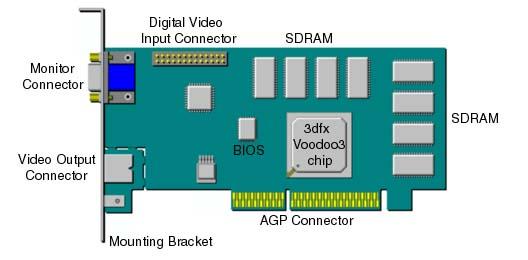
Voodoo3 3000 AGP

Voodoo3 2000 AGP
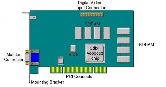
Voodoo3 2000 PCI
A diagram of the Monitor Connector on your Voodoo3 card and a table of the corresponding display signals is shown below.
 |
Pin 1 | Red |
| Pin 2 | Green | |
| Pin 3 | Blue | |
| Pin 4 | (none) | |
| Pin 5 | Self Test | |
| Pin 6 | Red Return | |
| Pin 7 | Green Return | |
| Pin 8 | Blue Return | |
| Pin 9 | DDC power (+5V) | |
| Pin 10 | Digital Ground | |
| Pin 11 | Digital Ground | |
| Pin 12 | DDC-2B Data | |
| Pin 13 | Horizontal Sync. | |
| Pin 14 | Vertical Sync. | |
| Pin 15 | DDC-2B Clock |
A diagram of the Digital Video Input Connector (CCIR-601) and a table of the corresponding signals is shown below:
 |
Pin 1 | Ground |
| Pin 2 | Data (0) | |
| Pin 3 | Ground | |
| Pin 4 | Data (1) | |
| Pin 5 | Ground | |
| Pin 6 | Data (2) | |
| Pin 7 | (none) | |
| Pin 8 | Data (3) | |
| Pin 9 | (none) | |
| Pin 10 | Data (4) | |
| Pin 11 | (none) | |
| Pin 12 | Data (5) | |
| Pin 13 | SCL | |
| Pin 14 | Data (6) | |
| Pin 15 | Ground | |
Pin 16 |
Data (7) | |
| Pin 17 | Ground | |
| Pin 18 | Video Clock | |
| Pin 19 | Ground | |
| Pin 20 | (none) | |
| Pin 21 | Ground | |
| Pin 22 | (none) | |
| Pin 23 | (none) | |
| Pin 24 | (none) | |
| Pin 25 | SDA | |
| Pin 26 | Ground |
Optional Video Output Connector
|
NOTE: This section describes an option that may not be supported by your model of the Voodoo3 card. |
A diagram of the optional Video Output Connector available on some models of the Voodoo3 3000 card is shown below:

The Optional Video Output Connector on the Voodoo3 3000 Card
|
NOTE: This section describes an option that may not be supported by your model of the Voodoo3 card. |
Use the optional Video Output Cable shown in the diagram to convert the S-video signal format of the optional Video Output Connector on some models of the Voodoo3 3000 card into a video line (composite video) signal for use with a standard TV or VCR.

The Optional Video Output Cable